2-Phase Step Motors / Drivers
Home > Products > Step Motors / Drivers > 2-Phase Step Motors / Drivers
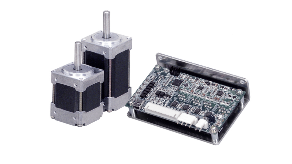
2-Phase Step Motors / Drivers
High accuracy, High torque, and High speed.
Features
- Step motors are able to start and stop, rotate and reverse.
- Rotational angle is proportional to the number of input pulses.
- Rotational speed is proportional to the input pulse rate.(pulse ratio)
- Even in the state of non-exciting, some self-holding torque(Detent torque) is generated because the permanent magnet is used.
- High torque, high response and light weight.
- Micro step drive, high accuracy and less expensive.
- Maintenance-free because there is no mechanical defacement like a brush for a DC motor.
2-Phase Step Motor Specification list
2-Phase Step Motor Specification list
|
Size
mm |
Step Angle
Deg. |
Model Number
|
Rated Voltage
V/Phase |
Rated Current
A/Phase |
Holding Torque
N・m (Kgf・cm) |
Body Size
mm |
|---|---|---|---|---|---|---|
|
□20
|
1.8
|
TS3692N1,N11
|
3.5
|
0.35
|
0.013 (0.13)
|
□20×30
|
|
TS3692N41,N51
|
3.0
|
0.35
|
0.017 (0.17)
|
□20×30
|
||
|
TS3692N2,N12
|
7.0
|
0.35
|
0.024 (0.24)
|
□20×46.5
|
||
|
TS3692N42,N52
|
5.6
|
0.35
|
0.032 (0.32)
|
□20×46.5
|
||
|
□28
|
1.8
|
TS3641N1E1,N11E1
|
1.05
|
1.5
|
0.05(0.5)
|
□28×33.5
|
|
TS3641N1E2,N11E2
|
2.6
|
0.95
|
0.06(0.6)
|
□28×33.5
|
||
|
TS3641N2E3,N12E3
|
1.4
|
0.09(0.9)
|
□28×47.5
|
|||
|
□35
|
1.8
|
TS3214N12
|
4.3
|
1
|
0.18(1.8)
|
□35×40.0
|
|
TS3214N13
|
12
|
0.19
|
0.058(0.58)
|
□35×25.4
|
||
|
TS3214N15
|
24
|
0.12(1.2)
|
□35×40.0
|
|||
|
TS3214N16
|
3.2
|
0.35
|
0.058(0.58)
|
□35×25.4
|
||
|
Φ36
|
0.9
|
TS3636N2
|
6.1
|
0.35
|
0.04(0.4)
|
Φ36×14.0
|
|
TS3636N3
|
3.6
|
0.33
|
0.068(0.68)
|
Φ36×19.6
|
||
|
□39
|
0.45
|
TS3216
|
9
|
0.24
|
0.035(0.35)
|
□39×27.0
|
|
TS3216N1
|
12
|
0.3
|
0.033(0.33)
|
□39×22.0
|
||
|
0.9
|
TS3166
|
0.32
|
0.05(0.5)
|
|||
|
TS3166N17
|
6
|
0.3
|
□39×25.5
|
|||
|
TS3166N18
|
1.1
|
0.8
|
||||
|
TS3166N20
|
8.8
|
0.35
|
0.08(0.8)
|
□39×32.0
|
||
|
1.8
|
TS3139N11
|
12
|
0.32
|
0.085(0.85)
|
||
|
TS3139N13
|
0.4
|
0.2(2.0)
|
□39×37.0
|
|||
|
Size
mm |
Step Angle
Deg. |
Model Number
|
Rated Voltage
V/Phase |
Rated Current
A/Phase |
Holding Torque
N・m (Kgf・cm) |
Body Size
mm |
|
□42
|
1.8
|
TS3617N1E1,N11E1
|
4
|
0.95
|
0.16(1.6)
|
□42×33
|
|
TS3617N1E2,N11E2
|
9.6
|
0.4
|
||||
|
TS3617N1E3,N11E3
|
12
|
0.3
|
||||
|
TS3617N2E4,N12E4
|
4
|
1.2
|
0.26(2.6)
|
□42×39
|
||
|
TS3617N2E5,N12E5
|
6.4
|
0.8
|
||||
|
TS3617N2E6,N12E6
|
12
|
0.4
|
||||
|
TS3617N2E7,N12E7
|
24
|
0.2
|
||||
|
TS3617N3E8,N13E8
|
4
|
1.2
|
0.32(3.2)
|
□42×47
|
||
|
TS3617N3E9,N13E9
|
7.2
|
0.8
|
||||
|
TS3617N3E10,N13E10
|
12
|
0.4
|
||||
|
□42
Hi Torque |
1.8
|
TS3617N502,N602
|
4.8
|
1.2
|
0.35(3.5)
|
□42×41
|
|
TS3617N503,N603
|
5.8
|
0.49(4.9)
|
□42×49
|
|||
|
TS3617N504,N604
|
7.2
|
0.75(7.5)
|
□42×61
|
|||
|
□42
Gearhead |
0.18
|
TS3631N210E1
|
4
|
0.95
|
0.736(7.5)
|
□42×58.2
|
|
0.1
|
TS3631N218E1
|
0.883(9.0)
|
||||
|
Φ46
|
0.9
|
TS3218
|
5
|
0.25
|
0.045(0.45)
|
Φ46×13.0
|
|
TS3218N5
|
12
|
0.075
|
0.045(0.45)
|
|||
|
1.8
|
TS3118N35
|
0.165
|
0.035(0.35)
|
|||
|
Size
mm |
Step Angle
Deg. |
Model Number
|
Rated Voltage
V/Phase |
Rated Current
A/Phase |
Holding Torque
N・m (Kgf・cm) |
Body Size
mm |
|
□50
Hi Torque |
1.8
|
TS3621N1,N11
|
2.2
|
2.0
|
0.32(3.2)
|
□50×40
|
|
TS3621N2,N12
|
3.2
|
0.65(6.5)
|
□50×55
|
|||
|
□56.4
|
1.8
|
TS3103N2E9
|
6.0
|
1.0
|
0.29(2.9)
|
□56.4×38.1
|
|
TS3103N1E13
|
5.1
|
0.4(4.0)
|
□56.4×50.8
|
|||
|
TS3103N255
|
24.0
|
0.3
|
0.65(6.5)
|
|||
|
TS3103N40
|
6.0
|
1.2
|
0.5(5.0)
|
□56.4×57.0
|
||
|
TS3103N3E1
|
1.7
|
4.7
|
0.72(7.2)
|
□56.4×76.2
|
||
|
TS3103N3E2
|
4.7
|
1.8
|
||||
|
TS3103N290
|
2.2
|
2.5
|
0.72(7.2)
|
|||
|
TS3103N4E11
|
2.5
|
4.6
|
1.08(10.8)
|
□56.4×101.6
|
||
|
TS3103N4E12
|
3.4
|
2.9
|
||||
|
□56.4
Hi Torque |
0.9
|
TS3690N1E1,N11E1
|
5.4
|
1.0
|
0.45(4.5)
|
□56.4×39
|
|
TS3690N1E2,N11E2
|
2.8
|
2.0
|
||||
|
TS3690N1E3,N11E3
|
1.6
|
3.0
|
||||
|
TS3690N2E4,N12E4
|
7.4
|
1.0
|
0.95(9.5)
|
□56.4×54
|
||
|
TS3690N2E5,N12E5
|
3.6
|
2.0
|
||||
|
TS3690N2E6,N12E6
|
2.3
|
3.0
|
||||
|
TS3690N3E7,N13E7
|
8.6
|
1.0
|
1.45(14.5)
|
□56.4×76
|
||
|
TS3690N3E8,N13E8
|
4.5
|
2.0
|
||||
|
TS3690N3E9,N13E9
|
3.0
|
|||||
|
Size
mm |
Step Angle
Deg. |
Model Number
|
Rated Voltage
V/Phase |
Rated Current
A/Phase |
Holding Torque
N・m (Kgf・cm) |
Body Size
mm |
|
□56.4
Hi Torque |
1.8
|
TS3653N1E1,N11E1
|
5.2
|
1.0
|
0.39(3.9)
|
□56.4×39
|
|
TS3653N1E2,N11E2
|
2.8
|
2.0
|
||||
|
TS3653N1E3,N11E3
|
1.9
|
3.0
|
||||
|
TS3653N2E4,N12E4
|
7.2
|
1.0
|
0.9(9.0)
|
□56.4×54
|
||
|
TS3653N2E5,N12E5
|
3.6
|
2.0
|
||||
|
TS3653N2E6,N12E6
|
2.3
|
3.0
|
||||
|
TS3653N3E7,N13E7
|
8.2
|
1.0
|
1.35(13.5)
|
□56.4×76
|
||
|
TS3653N3E8,N13E8
|
4.5
|
2.0
|
||||
|
TS3653N3E9,N13E9
|
3.0
|
|||||
|
TS3653N4E12,N14E12
|
2.2
|
5.0
|
2(20.0)
|
□56.4×84
|
||
|
□60
Hi Torque |
1.8
|
TS3606N1E1,N11E1
|
5.8
|
1.0
|
0.75(7.5)
|
□60×43.5
|
|
TS3606N1E2,N11E2
|
2.9
|
2.0
|
||||
|
TS3606N1E3,N11E3
|
1.95
|
3.0
|
||||
|
TS3606N2E4,N12E4
|
7.9
|
1.0
|
1.35(13.5)
|
□60×54
|
||
|
TS3606N2E5,N12E5
|
4.0
|
2.0
|
||||
|
TS3606N2E6,N12E6
|
2.55
|
3.0
|
||||
|
TS3606N3E7,N13E7
|
9.4
|
1.0
|
1.7(17.0)
|
□60×65
|
||
|
TS3606N3E8,N13E8
|
4.6
|
2.0
|
||||
|
TS3606N3E9,N13E9
|
2.9
|
3.0
|
||||
|
TS3606N4E10,N14E10
|
12.5
|
1.0
|
2.2(22.0)
|
□60×85
|
||
|
TS3606N4E11,N14E11
|
6.0
|
2.0
|
||||
|
TS3606N4E12,N14E12
|
3.9
|
3.0
|
||||
|
Size
mm |
Step Angle
Deg. |
Model Number
|
Rated Voltage
V/Phase |
Rated Current
A/Phase |
Holding Torque
N・m (Kgf・cm) |
Body Size
mm |
|
□86
Hi Torque |
1.8
|
TS3684N1E3,N11E3
|
1.8
|
4.5
|
2.5(25.0)
|
□86×79
|
|
1.28
|
6.4
|
3.5(35.0)
|
||||
|
2.56
|
3.2
|
|||||
|
TS3684N2E6,N12E6
|
2.8
|
4.5
|
5.5(55.0)
|
□86×117.5
|
||
|
1.98
|
6.4
|
7.8(78.0)
|
||||
|
3.97
|
3.2
|
|||||
|
TS3684N3E8,N13E8
|
3.36
|
4.0
|
7.5(75.0)
|
□86×156
|
||
|
2.39
|
5.7
|
10.6(106.0)
|
||||
|
4.7
|
||||||
2-Phase Step Motor / Driver applicable table
Bipolar type ※1
|
|
Micro-step
|
Micro-step
|
Micro-step
|
|---|---|---|---|
|
Driver model number
|
AU9290N2□□
|
AU9290N4□□
|
NEW!!AU9300
|
|
Input current
|
DC15~28V
|
DC30~50V
|
DC15~55V
|
|
Current consumption
|
2.4A rms
|
2.0A rms
|
7.5A rms
|
|
Applicable motor
Size □25×22mm TSP2150 |
●
|
●
|
●
|
|
Applicable motor
Size 08 □20mm TS3692 |
●
(Only TYPE1) |
●
(Only TYPE1) |
●
|
|
Applicable motor
Size 11 □28mm TS3641 |
●
|
●
|
●
|
|
Applicable motor
Size 14 □35mm TS3214 |
●
|
●
|
●
|
|
Applicable motor
Size 15 φ36mm TS3636 |
●
|
●
|
●
|
|
Applicable motor
Size 16 □39mm TS3216, TS3166, TS3139 |
●
|
●
|
●
|
|
Applicable motor
Size 17 □42mm TS3617, TS3631 |
●
|
●
|
●
|
|
Applicable motor
Size 18 φ46mm TS3118, TS3218 |
●
|
●
|
●
|
|
Applicable motor
Size 20 □50mm TS3621 |
●
|
●
|
●
|
|
Applicable motor
Size 23 □56.4mm TS3690, TS3653 |
●
※2 |
●
※2 |
●
|
|
Applicable motor
Size 24 □60mm TS3606 |
●
※2 |
●
※2 |
●
|
|
Applicable motor
Size 34 □80mm TS3684 |
●
※2 |
●
※2 |
●
|
Unipolar type
|
Micro-step
|
Full step /Half step
|
|
|---|---|---|
|
Driver model number
|
NEW!!AU9290N1□□
|
AU9236N1
|
|
Input current
|
DC15~28V
|
DC24~48V
|
|
Current consumption
|
1.8A rms
|
10A Max.
|
|
Applicable motor
Size □25×22mm TSP2150 |
–
|
-
|
|
Applicable motor
Size 08 □20mm TS3692 |
●
(Only TYPE2) |
-
|
|
Applicable motor
Size 11 □28mm TS3641 |
●
|
-
|
|
Applicable motor
Size 14 □35mm TS3214 |
●
(Only TYPE2) |
-
※3 |
|
Applicable motor
Size 15 φ36mm TS3636 |
–
|
-
|
|
Applicable motor
Size 16 □39mm TS3216, TS3166, TS3139 |
●
(Only TYPE2) |
-
※3 |
|
Applicable motor
Size 17 □42mm TS3617, TS3631 |
●
|
-
|
|
Applicable motor
Size 18 φ46mm TS3118, TS3218 |
●
(Only TS3218) |
-
※3 |
|
Applicable motor
Size 20 □50mm TS3621 |
●
※2 |
●
|
|
Applicable motor
Size 23 □56.4mm TS3690, TS3653 |
●
(Only TYPE2) ※2 |
●
(Only E1,2,4,5,7,8) |
|
Applicable motor
Size 24 □60mm TS3606 |
●
※2 |
●
(Only E1,2,4,5,7,8,10,11) |
|
Applicable motor
Size 34 □80mm TS3684 |
●
(Only TYPE2) ※2 |
●
|
Micro-step
|
Full step /Half step
|
|
|---|---|---|
Driver model number
|
NEW!!AU9290N1□□
|
AU9236N1
|
Input current
|
DC15~28V
|
DC24~48V
|
Current consumption
|
1.8A rms
|
10A Max.
|
Applicable motor
Size □25×22mm TSP2150 |
–
|
-
|
Applicable motor
Size 08 □20mm TS3692 |
●
(Only TYPE2) |
-
|
Applicable motor
Size 11 □28mm TS3641 |
●
|
-
|
Applicable motor
Size 14 □35mm TS3214 |
●
(Only TYPE2) |
-
※3 |
Applicable motor
Size 15 φ36mm TS3636 |
–
|
-
|
Applicable motor
Size 16 □39mm TS3216, TS3166, TS3139 |
●
(Only TYPE2) |
-
※3 |
Applicable motor
Size 17 □42mm TS3617, TS3631 |
●
|
-
|
Applicable motor
Size 18 φ46mm TS3118, TS3218 |
●
(Only TS3218) |
-
※3 |
Applicable motor
Size 20 □50mm TS3621 |
●
※2 |
●
|
Applicable motor
Size 23 □56.4mm TS3690, TS3653 |
●
(Only TYPE2) ※2 |
●
(Only E1,2,4,5,7,8) |
Applicable motor
Size 24 □60mm TS3606 |
●
※2 |
●
(Only E1,2,4,5,7,8,10,11) |
Applicable motor
Size 34 □80mm TS3684 |
●
(Only TYPE2) ※2 |
●
|
Notices
※1: Bipolar type drivers can drive unipolar step motors other than TS3692 TYPE2 (5 wires).
※2:Motor current is limited by rated current of driver.
※3:Please use the constant voltage driver.
2-Phase Step Driver AU9290, AU9300 Series
AU9290 Series
Model number
|
AU9290N10□
|
AU9290N1□□
|
AU9290N2□□
|
AU9290N4□□
|
|---|---|---|---|---|
Input current
|
DC15~28V
|
DC15~28V
|
DC15~36V
|
DC30~50V
|
Motor type
|
2-phase unipolar
|
2-phase unipolar
|
2-phase bipolar / unipolar
|
2-phase bipolar / unipolar
|
Driving mode of
step motor |
Micro step constant current drive Step angle: 1/64 of a basic step angle
|
Micro step constant current drive Step angle: 1/64 of a basic step angle
|
Micro step constant current drive Step angle: 1/64 of a basic step angle
|
Micro step constant current drive Step angle: 1/64 of a basic step angle
|
Rated output current
|
1.8Arms
|
1.8Arms
|
2.4Arms
|
2.0Arms
|
Usage environment
|
Ambient temp. : 0 ~ 50℃,Humidity : 90%RH or lower (No condensation)
|
Ambient temp. : 0 ~ 50℃,Humidity : 90%RH or lower (No condensation)
|
Ambient temp. : 0 ~ 50℃,Humidity : 90%RH or lower (No condensation)
|
Ambient temp. : 0 ~ 50℃,Humidity : 90%RH or lower (No condensation)
|
AU9300 Series
|
Model number
|
AU9300
|
|---|---|
|
Input current
|
DC15~55V
|
|
Motor type
|
2-phase bipolar / unipolar
|
|
Driving mode of
step motor |
Micro step constant current drive Step angle: 1/64 of a basic step angle
|
|
Rated output current
|
7.5Arms
|
|
Usage environment
|
Ambient temp. : 0 ~ 50℃,Humidity : 90%RH or lower (No condensation)
|
Function & Performance list of AU9290, AU9300 Series
AU9290N10□ (Low price type)
Model number
|
N100,101,102
|
N103,104
|
N105,106
|
|---|---|---|---|
Pulse Input
|
2 points(Isolated)
Frequency : 1.0MHz Max. |
2 points(Isolated)
Frequency : 1.0MHz Max. |
Unprovided
|
Digital input
|
1 point(Isolated)
|
5 points(Isolated)※
|
1 point(Isolated)
|
Digital output
|
Unprovided
|
Unprovided
|
Unprovided
|
Communication function
|
Unprovided
|
Unprovided
|
RS485
|
Connection to PC
|
USB2.0( Full speed)
|
USB2.0( Full speed)
|
USB2.0( Full speed)
|
Protective function
|
Over current, Overload, Step-out, Current control error, Current offset error, Overheat, Over voltage, Power down, Parameter error, Memory error.
|
Over current, Overload, Step-out, Current control error, Current offset error, Overheat, Over voltage, Power down, Parameter error, Memory error.
|
Over current, Overload, Step-out, Current control error, Current offset error, Overheat, Over voltage, Power down, Parameter error, Memory error.
|
Parameter storage
|
Stored in a buit-in EEPROM
|
Stored in a buit-in EEPROM
|
Stored in a buit-in EEPROM
|
Status display
|
Two – color LED×1
|
Two – color LED×1
|
Two – color LED×1
|
Other than AU9290N10□
|
Model number
|
N20□,N40□
|
N□1□
|
N□2□
|
N□3□
|
|---|---|---|---|---|
|
Pulse Input
|
2 points(Isolated)
Frequency : 1.0MHz Max. |
2 points(Isolated)
Frequency : 1.0MHz Max. |
2 points(Isolated)
Frequency : 1.0MHz Max. |
2 points(Isolated)
Frequency : 1.0MHz Max. |
|
Digital input
|
1 point(Isolated)
|
5 points(Isolated)
|
1 point(Isolated)
|
1 point(Isolated)
|
|
Digital output
|
Unprovided
|
1 point(Isolated)
|
Unprovided
|
Unprovided
|
|
Communication function
|
Unprovided
|
Unprovided
|
RS485
|
RS232C
|
|
Connection to PC
|
USB2.0( Full speed)
|
USB2.0( Full speed)
|
USB2.0( Full speed)
|
USB2.0( Full speed)
|
|
Protective function
|
Over current, Overload, Step-out, Current control error, Current offset error, Overheat, Over voltage, Power down, Parameter error, Memory error.
|
Over current, Overload, Step-out, Current control error, Current offset error, Overheat, Over voltage, Power down, Parameter error, Memory error.
|
Over current, Overload, Step-out, Current control error, Current offset error, Overheat, Over voltage, Power down, Parameter error, Memory error.
|
Over current, Overload, Step-out, Current control error, Current offset error, Overheat, Over voltage, Power down, Parameter error, Memory error.
|
|
Parameter storage
|
Stored in a buit-in EEPROM
|
Stored in a buit-in EEPROM
|
Stored in a buit-in EEPROM
|
Stored in a buit-in EEPROM
|
|
Status display
|
Two – color LED×1
|
Two – color LED×1
|
Two – color LED×1
|
Two – color LED×1
|
Parameters can be set and data can be monitored
|
Operating mode
|
Position command mode or speed command mode
|
|---|---|
|
Pulse command
mode |
F-Pulse/R-Pulse or Pulse/Direction
|
|
Position data
resolution |
Set to be the integer multiple of basic number of steps
|
|
Motor current
|
Rotating Motor Current and Stopping Motor Current with the value of ratio for motor rated current.
|
|
Movement pattern
|
Moving speed, minimum speed, acceleration and deceleration
|
|
Origin search
operation |
Port asignment of origin signal and homing start signal, signal polarities and homing direction.
|
|
Communication
protocol |
Selection for communication protocol from TSC standard or Modbus.
|
|
UART setting
|
Baud rate, parity and number of stop-bit.
|
|
Motor parameter
|
Rated current, winding resistance, winding inductance and basic number of steps
|
|
Monitor for operating
conditions |
Power voltage, temperature around power devices, driver status, etc.
|
|
Monitor for control data
|
Actual-Motor-Position, Target-Position, Actual-Motor-Current, etc.
|
|
Monitor for
alarm history |
Possible to monitor last 32 alarm codes.
|
Notices
※Pulse input circuits are shared with digital input circuits in case of AU9290N103 and N104.
Users Manual・Set up software download
Specification of AU9236N1 Series
|
Driving mode
|
Full step / Half step
|
|---|---|
|
Driver model number
|
AU9236N1
|
|
Input current
|
DC 24~48V
|
|
Output current
|
2.0~5.0A Max./ Phase
|
|
Excitation method
(Set by dip switch) |
1-2 phase excitation / 2-phase excitation (shipping mode)
|
|
Input signal circuit
|
Photo-coupler, input resistance 220 Ω ,
input current ranging between 10mA and 20mA |
|
Input signal
(Set by dip switch) |
CW、CCW input method(2clock method)/PULSE、DIR method(1clock method)Switching
|
|
Output signal、Current-setting terminal (IS)
|
IM (Driving current) (A) = Terminal source (V)×2-1
|
|
Overheat prevention function
|
A red LED lights up and the motor
stops automatically when a heatsink excessively heats up. |
|
Automatic current-down
(Set by dip switch) |
ON(shipping mode)/OFF Switching
In operation, Output current decreases to about 50% normal rate about 1 sec. after first transition of input pulse. |
|
In operation temp./humidity
|
0~40℃ 90%RHor lower (non condensing)
|
|
In storage temp./humidity
|
-20~60℃ (non condensing)
|
Innovation, quality and efficiency paired with high resistance and durability.
Since its foundation Tamagawa has taken up the challenge of further improving angular precision for control equipment such as high-precision sensors, motors and gyros. We are determined to satisfy your requirements with our high quality products by improving our technologies continuously and also constantly developing and applying new technologies. We can look back on an extensive industry-proven track record in all our fields of application.